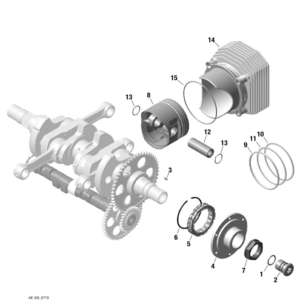
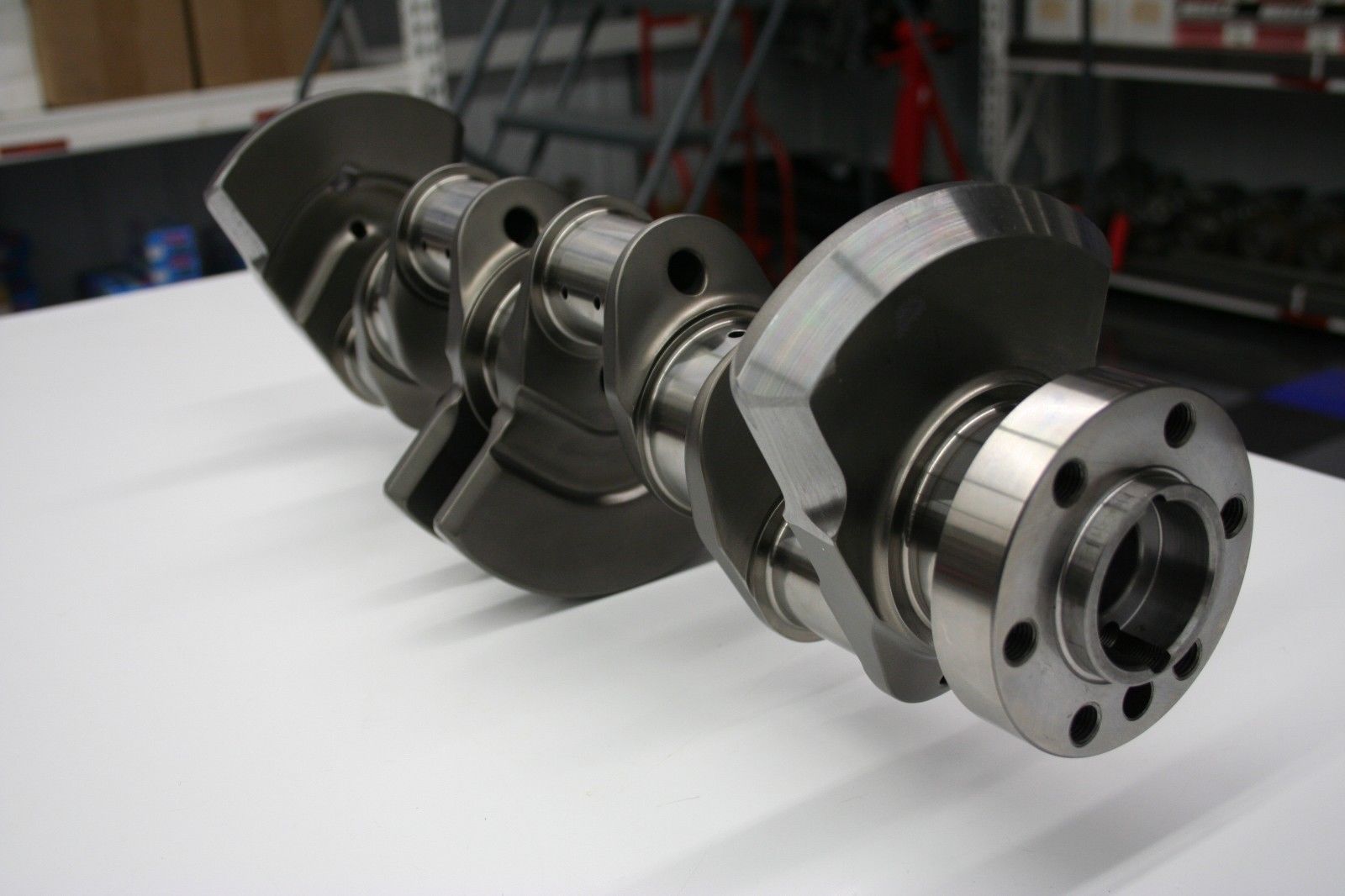
Crankshaft Aircraft - In reciprocating engines, the crankshaft works to convert the linear motion of the piston into rotary motion, resulting in the work done on the piston being useful for turning a gear or propeller. Although other devices have been attempted to achieve the transformation from reciprocating to rotary motion, the crankshaft is commonly used in piston engines today and has been ubiquitous in high-performance aircraft engines. In inline aircraft engines, the crankshaft was often the heaviest single component, making it a target for weight reduction despite limitations imposed by other design factors. These may include cylinder spacing (control overall length), trunnion sizes to provide adequate bearing area, and the need to provide counterweights to reduce bearing loads. Despite these limitations, the Rolls-Royce Merlin Crank with eight counterweights weighed only four pounds more than the Liberty-12 without a counterweight (107 versus 103 pounds). Both engines had almost the same displacement, with the Merlin eventually close to 2,000 horsepower and the Liberty 420 horsepower. The Liberty was designed in 1917 and the Merlin design began in 1933.
The crankshaft was developed during a time when the ability to predict and measure tension was very limited. There was limited knowledge about stress concentration factors and no practical way to measure stress in static testing of crankshaft elements. All the designer had to go by was what had worked in the past. Nominal working voltages can be calculated based on estimated cylinder pressures and inertial loads, and the US Army Air Corps has standardized formal procedures for doing so. Finally, in the late 1930s, experimental stress analysis began to be incorporated into the design process. These techniques include the use of photoelasticity, brittle stress layer, mechanical extensometers for strain measurements, and electrical strain gauges. However, prior to the use of most of these devices, the fundamental evaluation of crankshaft design was established in a large European paper that subjected various crankshaft configurations to fatigue failure. This work had an impact on the design of all types of crankshafts, as well as German military aircraft engines, and will be discussed later in this paper.
Crankshaft Aircraft

The crankshaft is an excellent example of a highly loaded and complex machine element. Its evolution spans a much longer period of time than we consider here, but the period of high-performance aircraft piston engines fueled its development more rapidly than at any other time. In addition to design refinements, this activity includes forging techniques, metallurgy, heat treatment, and the effects of shot peening and nitrides on crankshaft fatigue strength.
How The Crankshaft Works
Figure 1 shows two attempts to remove the crankshaft, both with airplanes as the target market and both claiming low frontal area as their advantage. The first, the Fairchild-Caminez engine of the late 1920s, was actually certified and flight-tested, but had very high fourth-order torque due to the two-lobe cam and relatively heavy piston assembly. and (1) was disobeyed. The other engine shown is a barrel type known as an Alfaro engine and dates from the late 1930s (2). There have been many attempts to use the swash plate mechanism shown here in piston engines, but none have been successful, usually due to high tensions at the point of contact between the connecting rod and the cam or swash plate. The maintenance of such an engine also seems to be a problem. An application where this configuration has proven very successful is in automotive air conditioning compressors, where the loads are much lower than in engines.
Several factors go into selecting the relative orientation of the cranks on the crankshaft of a multi-cylinder engine. These include:
Some of these required compromises to be made and led to significant development work on some engines.
Our task was made a little easier by the fact that most later engines had cylinders that were either 6, V-12, or flat twelve configurations, all of which used a six-throw crank, as shown in Figure 2.
How It's Done
The six-shot crank is symmetrical; after the first three sticky notes, the other three sticky notes are a mirror image of the first three. The only possible variation is if the pair of pitches marked 3, 4 with the two marked 2, 5. This crank provides completely balanced first and second order forces and moments. There are a large number of possible firing orders for this crank. The bank angle increases the possibilities, but most were 60° with the notable exception of the Liberty 12 which had a 45° bank angle and uneven firing order.
As shown in Figure 2, the six-throw crank has seven main bearings, and all the engines discussed in this paper had this number. The Curtiss K-12 had four main bearings and is the only aircraft engine with a six-shot crank that uses that many main bearings that I know of. Four main bearings on six throw rods were much more common in automotive applications.
The four-throw crank in Figure 2 is also symmetrical with respect to its central principle. This is the configuration used in all modern straight-four engines and was used in the Hispano-Suiza V-8 aircraft engines of World War I and later. The Napier Lion, which was a W-12 with three banks of four cylinders, was also designed during World War I and was flown into the late 1920s; it also uses the four-throw flat crankshaft with five mains as shown in Figure 2. The Hispano and Lion engines had unbalanced second-order jolt forces due to this crankshaft configuration. Modern V-8 engines use an antisymmetric shaft with 90° throw and counterweight to balance the rotating masses, effectively eliminating first- and second-order forces and moments. The Wright Company was the licensee of the Hispano engines and reportedly built a prototype with an antisymmetric crankshaft to eliminate second order forces, but did not follow this approach as they felt it would add too much weight to the engine ( 3).

To illustrate the choices made in choosing firing orders, crank orientations, and counterweights, I chose three late-inline-configuration-era V-12 engines. These are shown schematically in Figure 3. The Rolls-Royce Griffon is the last engine of its type designed, developed and saw extensive service after the Second World War.
Supercharger 1800 Billet Crankshaft Forged Pistons Connecting Rod For Pwc Jet Ski Seadoo Waverunner Yamaha Parts Conrod Svho Gp
Note that none of these engines have the same firing order, and the Rolls-Royce Merlin's crankshaft arrangement is different from the Allison V-1710 and Griffon. The Allison engine also initially had six counterweights, which increased to twelve in its later configurations, the Merlin had eight and the Griffon four. The question naturally arises, if these engines had no primary or secondary unbalance, why did any arrangement within the limits imposed by the symmetrical six-shot crank differ from another? The answer lies in the bending and torsional flexibility of the crankshaft and crankcase. Examine Figure 2, it will be seen that the opposite pull of the crankshaft members create an internal bending moment that must be balanced in the main bearing, unless the crankshaft is infinitely rigid when bending. Similarly, the alternating first- and second-order forces of piston motion across the crankcase must balance, even though the net external effect is zero. The crankcase, like the crankshaft, is not infinitely rigid and significant deflections occur when loads are applied to the main bearings.
Crankshaft runout can be mitigated somewhat with counterweights and most later engines had them, especially when piston speed approached 3,000 feet per minute. These have been carefully rated to be large enough to minimize bearing wear without adding excess weight to the axle. I don't know of engines where the counterweights completely balance the total rotational inertia. However, if the crankcase is too flexible, the crankcase can slip off the line of the shaft and cause edge strain on the bearings.
The Griffon engine seems to have required considerably more development than either the Allison or the Merlin (4) in this regard. The crankshaft arrangement and firing order shown in Figure 3 represent the latest in a long series of changes. The original Griffon had the same crank arrangement and firing order as the Merlin. The firing order was changed as friction occurred in the transmission from the rod shaft to the reduction gears and this was attributed to torsional vibrations. Problems continued with cylinder head cracks due to excessive crankcase deflections. The crankcase was hardened and the four-mass counterweight system was designed. The firing order shown in Figure 3 was finally adopted, the last of at least four iterations.
The effect of firing order on torsional vibration is illustrated in Figure 3 by the phase angle diagrams for the different vibration orders. The diagrams show how the contributions of different cylinders are combined to give the total excitation for a given vibration order. If the crankshaft were infinitely stiff in torsion, only the main order would exist
Crankshaft Aircraft Engine On Gray Background Stock Vector (royalty Free) 1325753357
Hotrods crankshaft, subaru crankshaft, crankshaft lenses, aircraft crankshaft, caterpillar crankshaft, oakley crankshaft, 3406b crankshaft, aircraft crankshaft repair, crankshaft machining, n14 crankshaft, crankshaft grinding, crankshaft balancer
0 Comments